Making a flight controller for RC Helicopters
Background
Back in october of 2023 i made the decision to come back to RC flying after a long time of building up bikes and “recovering” from my FPV racing endeavours. I’ve had a growing interest in 3D Helicopters and have been flying an OMPHobby M1 evo for a good bit, it felt like a natural decision to upgrade in size a bit. OMPHobby did make a larger heli, the M4 and with it both being a company i knew and being designed by a fellow german pilot i went for it! Now, usually 3D helicopter flight control systems are closed source and quite expensive but through looking around a bit i stumbled over the Rotorflight project. Now when i started looking at Rotorflight there were not that many flight controller options available for purchase yet. And due to those not quite being what i wanted i made the decision to design my own…
Considerations
Luckily, a good chunk of the work has already been done for me by the Rotorflight dev team. There are two very extensively documented reference designs aswell as nicely laid out FC design requirements (tho i believe that they have been updated after i built my FC). I wanted my flight controller to be a very simple design with no unnecessary features. I may have kept it a little too simple but in the end i’m still happy with the desing!
Naming isn’t exactly my strong suit but i believe i figured out something nice here. With how agile these modern Helicopters are my brain jumped to bird names. Sparrowhawks are fairly common in my home region and their genus “Accipiter” hand a nice ring to it. Accipiter F7 is a name that i’m really happy with!
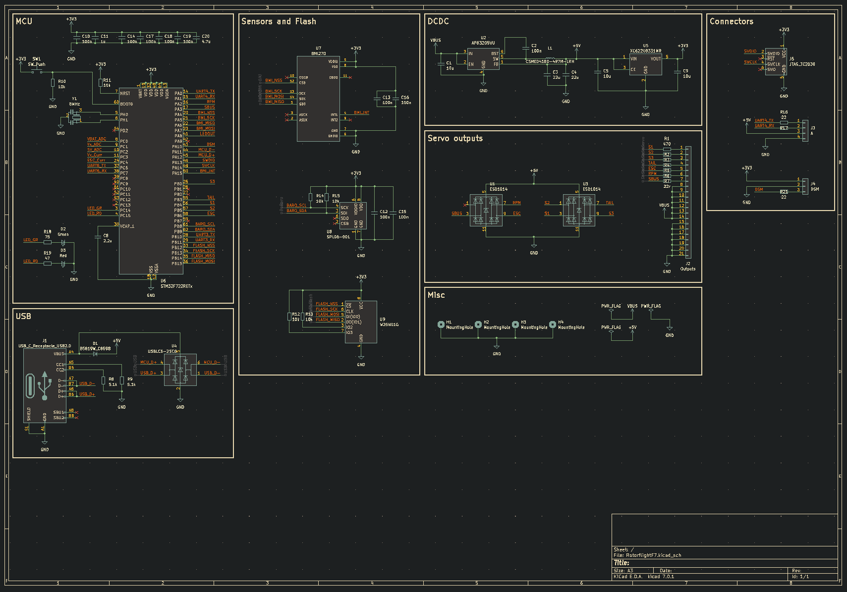
Schematic
The flight controller is fully designed in KiCAD EDA. It’s a pretty standard STM32F722 design plus a BMI270 gyro, a SPL06 barometer and a W25N01G for 125mb of flash storage (datalogging). The TypeC connector is a 12pin HRO TYPE-C-31-M-12 which has been my favourite USBC connector for up to USB2 for a while now. Behind that, an ESD protection diode array to protect from transient voltage spikes.
Btw, if you ever do a design with USB C, PLEASE make sure to correctly setup your CC lines. For most USB 2 devices, a 5.1k Resistor to ground on CC1 and CC2 will be sufficient. If you forget this, your device will only work on USB A to C cables (or any port that doesn’t follow the typeC standard).
The Servo signals have their own ESD and overcurrent Protection implemented with ESD1014s and one 470R resistor per channel (except for the SBUS (RS232-ish) signal input for which 470R would be much too high). Apart from that, the flight controller only has a few extra connectors for receivers and SWD aswell as some Status LEDs.
Design
First, i played around with having a longer design using 90deg servo headers but that resulted in a FC that was VERY long. I also figured out that i really didn’t need that many expansion ports for my application, it was gonna be a pure sport flying FC, no need for GPS or other additions.
This design also had no real consideration for a case, i just assumed i could make a snap fit 3D Printed enclosure… which really isn’t very elegant or good looking. So after narrowing down what i didn’t like about this design i set out to make something better…
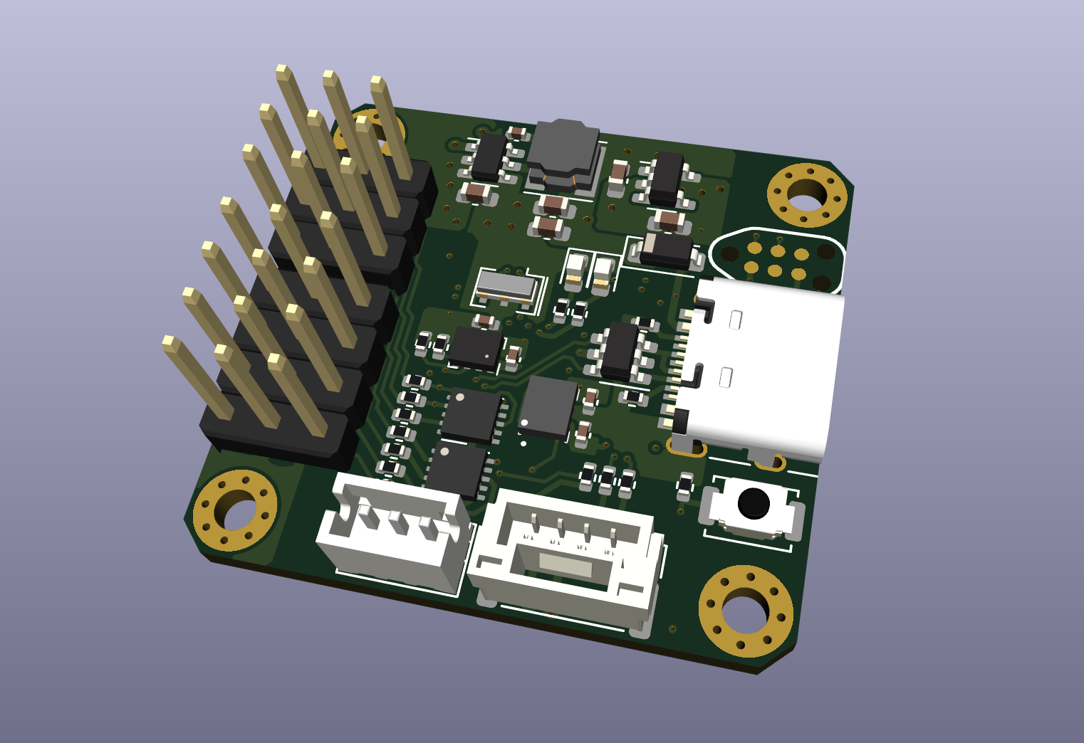
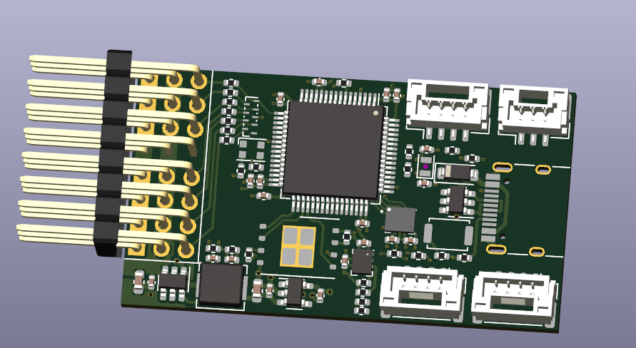
This design added the integrated ESD diodes, vertical servo headers and the convenient TC2030 probe header (which i never ended up using but hey, better to have it than to need it).
The STM32 and Flash moved to the bottom side of the board, increasing assembly costs but drastically reducing board size. I also added some M2 mounting holes for a future Enclosure which i set out to design next.
Enclosure
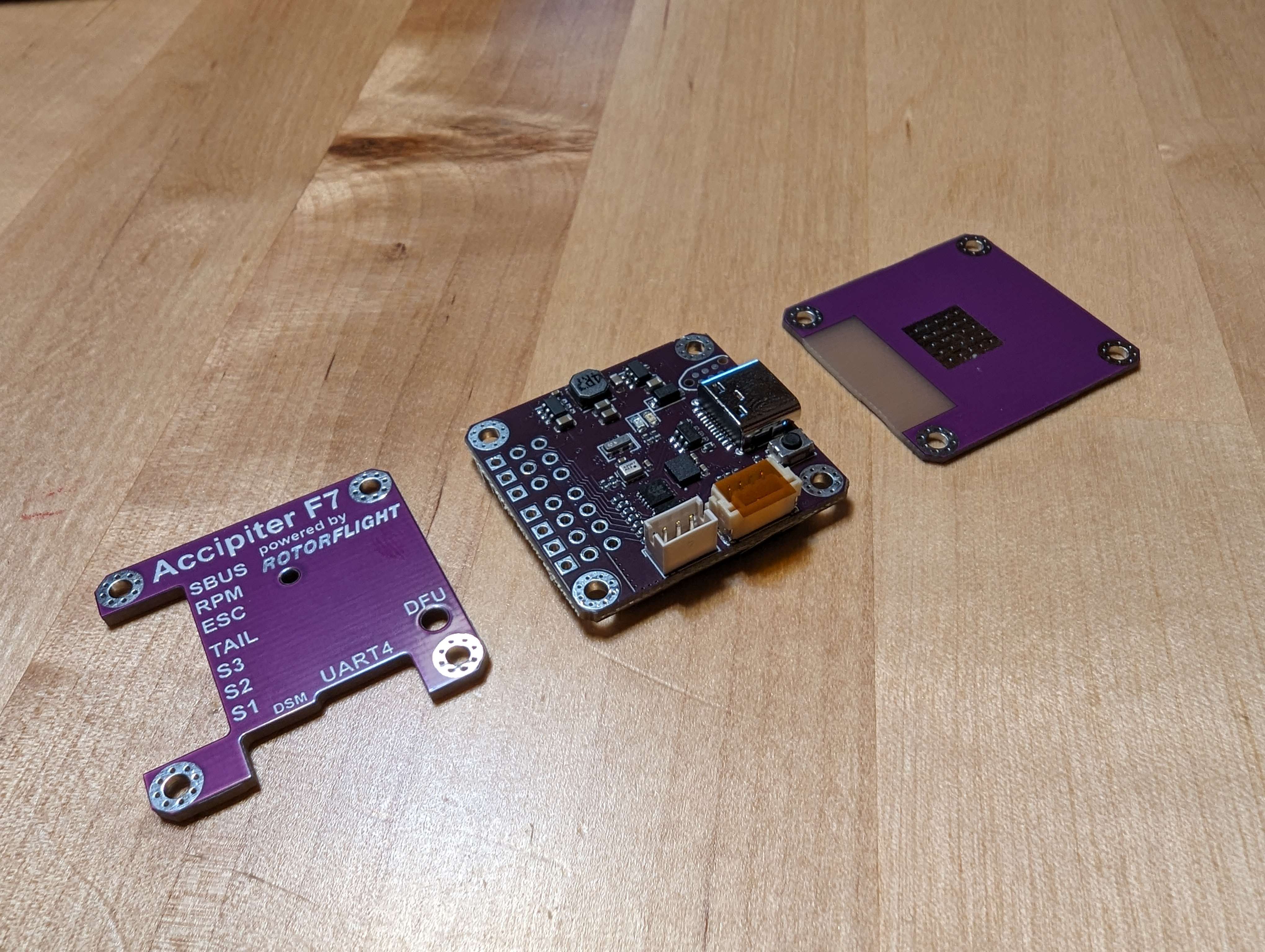
My usual enclosure design workflow is to throw the PCB into Fusion, offset some outlines and see where i get from there. I decided to only have the outer “ring” of the Enclosure be 3D printed and have the upper and lower plates be PCBs. That also allowed me to add the pinout and other Info on the Top PCB and to use the lower PCB as a heatsink for the STM32 (it does tend to run a little hot when fully enclosed).
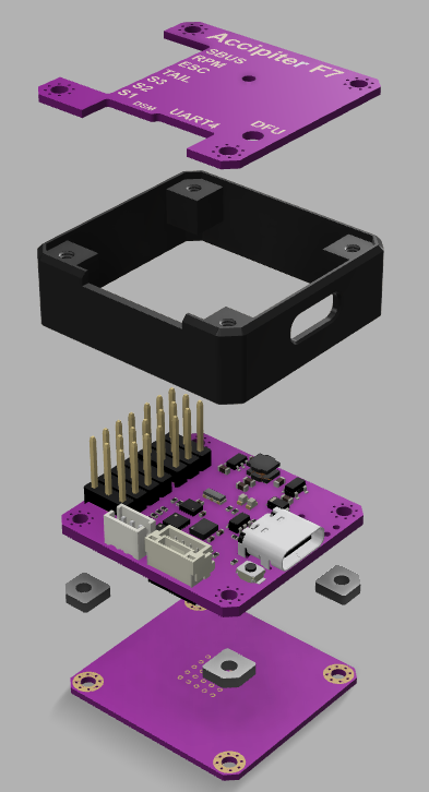
With minor changes you could have the 3D Printed case CNC cut, i decided that with how expensive the PCBs already were, i wouldn’t want to spend much more on such creature comforts.
Building the FCs
 So, this whole project started with me wanting to save some cash. 5 of those FCs assemlbed at JLCPCB and shipped to germany ended up costing me 350€… but hey, we’re already way too dep into the project to not order the hardware! On arrival, all the boards looked great and i got to flashing Rotorflight2 firmware onto them. Aaaaaand, on all of them the barometer didn’t work… which makes sense considering i had them assembled wrong. JLC engineers even warned me about it but i was so sure i was right! To my defense, the vent hole on the barometer very much looked like a pin1 indicator^^ You live and learn.
With the help of a little hot air i got those sorted pretty quickly and all the FCs were working great! Except for one where the BMI270 didn’t want to give me any gyroscope output:
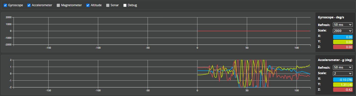
Since the accelerometer unit inside worked perfectly fine and all other FCs didn’t have this issue on the same firmware i assumed it was a hardware failure on the BMI270. I notified JLCPCB about it and we settled on a small Refund, enough for me to order a few bare BMIs and swap this one out. With that, i was ready to assemble the FC.
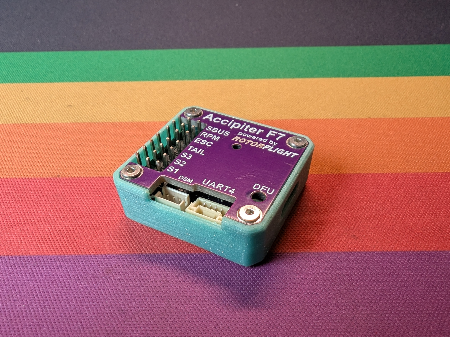
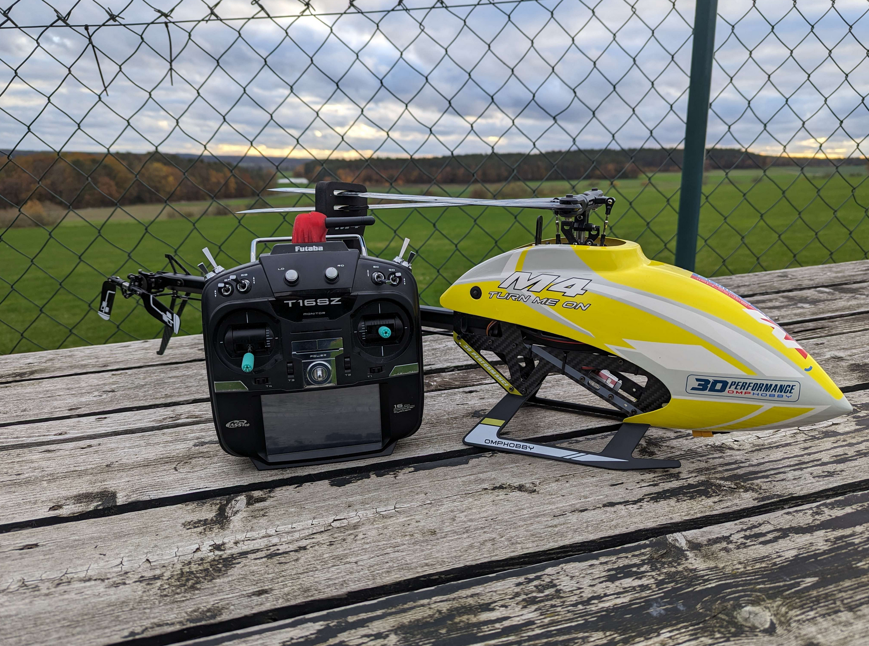
I was really happy with how they looked and all connections worked fine so it was time to put it into a helicopter! I got my M4 at Faszination Modellbau in Friedrichshafen (one of the biggest RC trade shows in europe) from RC-Hangar 15, a shop who’s owners i’ve known personally for years now and love to support. I also “accidentally” picked up a new transmitter, the Radiomaster Boxer, which by now has become my main radio for pretty much everything.
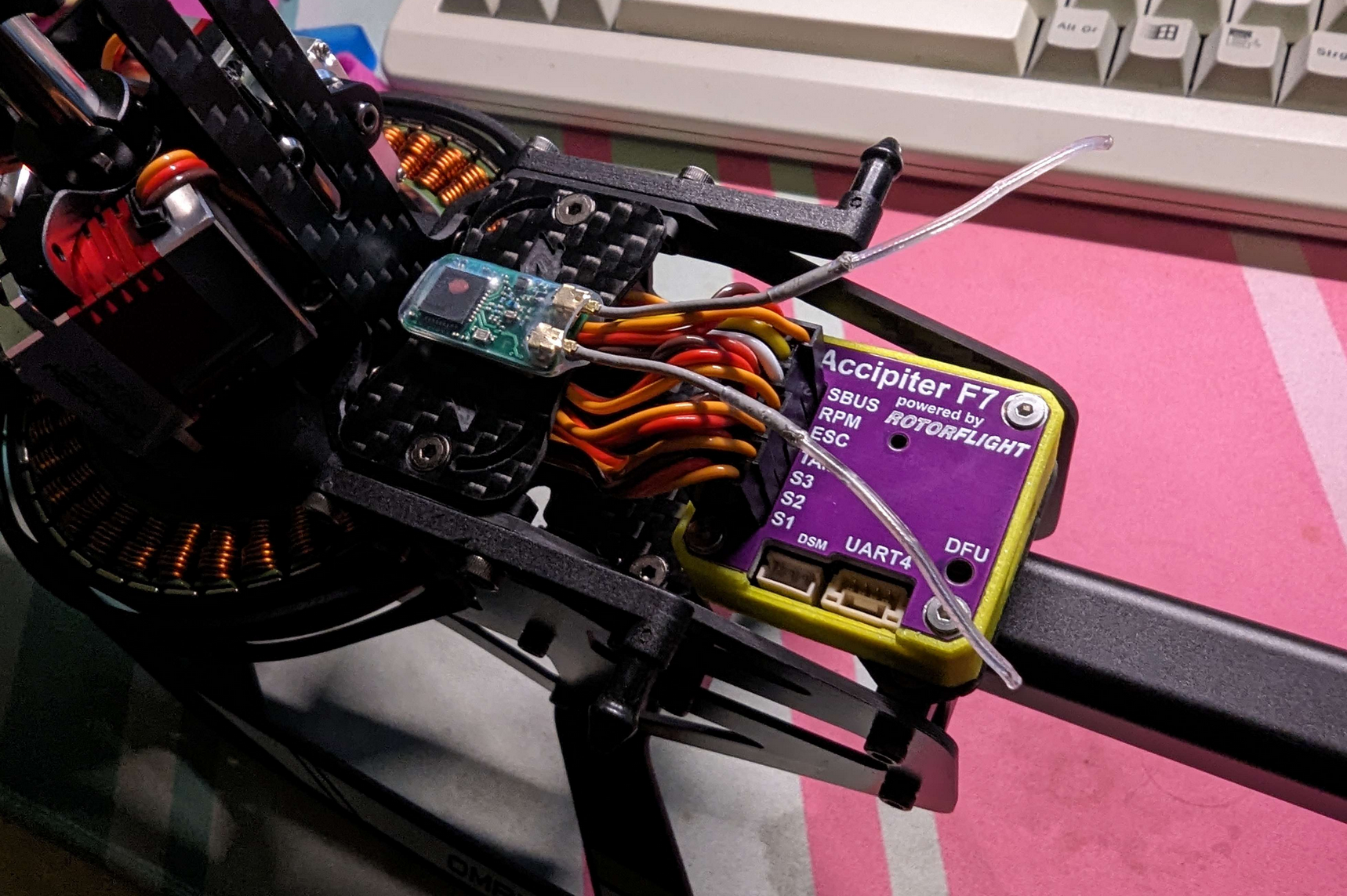
This really isn’t a post about building a helicpter (plus, i am quite inexperienced at that anyways). So here’s the FC (this time with a yellow print to match the heli) in the build and the obligatory last picture before the maiden flight.
Final Notes
Luckily everything went well on the test flight and even though the heli has kissed the ground a few times so far, i’ve always gotten it back up and running. Tuning isn’t my strong suit and mechanically, things could’ve been built better but i do love the process of constant improvement. I did buy a commercial flight controller a while later to compare and and was happy to see that the heli flew exactly the same, meaning that as suspected, i’m a much better electrical engineer than a heli builder.
The project cost ended up at around 2x the price of a commercial flight control system, but i can argue that i got 5 FCs out of it. So if i ever end up building more helis, i’m prepared!
Back in 2023 i still had plans of maybe finding a shop to sell this hardware but with how many (arguably better) commercial offerings are out there today i really don’t see it making any sense. I decided to open source the project on GitHub for people to adapt for their needs and play around with.
If you do end up creating something with it i’d love to hear about it on my socials, thanks for reading!